SF-V2M36-A
Hammered System
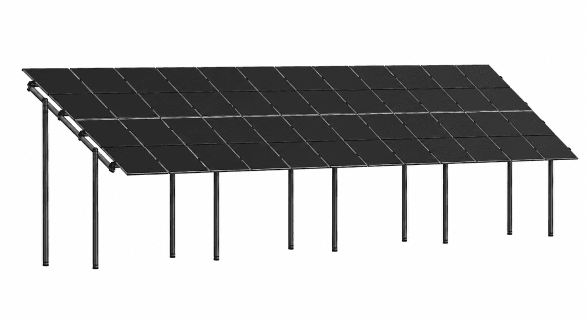
Commercial and utility-scale ground-mount system with steel piles installed directly into the ground.
Module Compatibility
Configuration reference
Reference module layout for the mono-facial, two-row, vertical SF-V2M36 configuration (applies to both the Hammered and 4Root variants of the frame):
| Module (mm) | Clearance “A” | Overhang “B” |
|---|---|---|
| 1134 × 1722 mm | 795 mm | 160 mm |
| 1134 × 1902 mm | 690 mm | 340 mm |
| 1134 × 2279 mm | Not suitable | Not suitable |
“A” = clearance from ground level, “B” = module overhang. Final module compatibility must be confirmed during engineering review for each project.
Key Benefits
Why this system
- No concrete foundation required.
- Steel supports are driven directly into suitable ground.
- Efficient installation for larger and repetitive layouts.
- 36° reference tilt configuration for Lithuanian conditions.
- Approximately five hours for an experienced team to assemble a typical 10 kW structure, where site and configuration conditions allow.
- SIGMA profile designed for improved bending and torsional resistance.
- Z330 galvanized steel protection.
How It Works
From foundation to finished frame
- Step 1
Single-piece steel piles are driven directly into the ground with pile-driving equipment — no concrete footings.
- Step 2
Longitudinal SIGMA-profile beams (single piece, up to 3615 mm) connect across the driven piles to form the support table.
- Step 3
An angular stabilizer and side longitudinal connection add stabilizing planes to the frame, increasing rigidity over a simple horizontal joint.
- Step 4
Modules are mounted in a vertical, two-row, mono-facial reference configuration at the standard 36° tilt.
Technical Specification
Specification table
| System code | SF-V2M36-A |
|---|---|
| Structure | Vertical, two-row, mono-facial reference configuration |
| Reference tilt | 36° (optimized for Lithuanian latitude) |
| Frame profile | SIGMA profile |
| Steel | DX51D Z330 galvanized, per EN 10346, or project-specific approved alternative |
| Steel member thickness | Project-specific — see engineering parameters belowProject-specific |
| Foundation / pile depth | Driven steel piles — depth is project-specific, see note belowProject-specific |
| Longest packaged part | 3615 mm (single-piece longitudinal beam) |
| Reference install time | ≈5 hours for an experienced team on a typical 10 kW structure, site-dependent |
| Standard | EN 10346 material standard; CE / EN 1090 manufacturing documentation where applicable |
| Verification | Engineering calculations and cooperation with Kaunas University of Technology (KTU) |
Project-specific engineering parameters
The supplied source documents give more than one value for the parameters below. Rather than publish a single number that may not match your project, we list what each document states and confirm the exact figure during engineering review.
Steel member thickness
Two configuration options are documented for the SF-V2M36 frame. The exact thickness used on a given project depends on load case, span, and site wind/snow requirements, and is confirmed during engineering review.
- Product overview sheet (apie solar.pdf) — Option 1: legs 3.0 mm, cross beams 2.0 mm, longitudinal 2.0 mm
- Product overview sheet (apie solar.pdf) — Option 2: legs 3.0 mm, cross beams 2.0 mm, longitudinal 1.5 mm
- SF-V2M36 technical sheet (V26_MF_KO-V2M36-sistemos): legs 2.5 mm, cross beams 2.5 mm, longitudinal 1.5 mm
Hammered pile embedment depth (SF-V2M36-A)
The technical sheet states an embedment depth of 1200 mm below ground in its specification text, while the accompanying dimension callout on the same drawing references a different figure. Final pile depth is confirmed per project based on soil conditions and structural calculation, not published here as a single universal value.
- SF-V2M36 technical sheet — specification text: 1200 mm below ground
- SF-V2M36 technical sheet — drawing dimension callout: Dimension callout on the same sheet differs from the text value; treat as unconfirmed
Engineering Features
Built into every frame
- SIGMA profile — approximately 14% higher bending resistance and 23% higher torsional resistance than a standard C-profile
- Angular stabilizer to reduce longitudinal torsion
- One-sided “Helicopter” clamp fastening
- Side longitudinal-profile connection for an additional stabilizing plane
- DX51D Z330 galvanized steel, per EN 10346
- Driven steel pile foundation — no concrete
Do not state one universal pile depth or metal thickness for this system — the supplied documents contain configuration-dependent values. See “Project-specific engineering parameters” below.
Request a Hammered System Quote
Send your project details and our engineering team will recommend the right configuration and provide a project-specific quotation.